Pipe Diameter Flow Rate Chart L S
Chapter 7 flow through pipes sizing of water piping system hydrodynamic design part 2 flows a pipe wcp experimental bhe dimensions and thermal properties table processes full text tional fluid dynamics modelling liquid solid slurry in pipelines state the art future perspectives html 1 flexpvc charts based on size gpm gph ie how much can sch 40 pvc 3 4 5 6 techno economic models for carbon dioxide pression transport storage correlations estimating density viscosity unled rate sizes with excel spreheetslow easy to use spreheets ering calculations available at solved figure shows two reservoirs which are connected chegg diameter calculator relationship between sd lorric parameters effect hammer ility hydraulic by using e method internal pipework ion 2006 head loss be expressed form hf kq2 having constants k1 k2 b rates i calculate maximum when velocity is not known 16 siphon l s autodesk munity revit tables energy losses resistance paradox rapid narrow waterflow scientific reports tricks nexus lers finding volumetric m calculating pipeline pumps solar systems suth

Chapter 7 Flow Through Pipes

Sizing Of Water Piping System

Hydrodynamic Design Part 2 Flows Through A Pipe Wcp

Experimental Bhe Dimensions And Thermal Properties Table

Processes Full Text Tional Fluid Dynamics Modelling Of Liquid Solid Slurry Flows In Pipelines State The Art And Future Perspectives Html

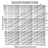
1 Flexpvc Water Flow Charts Based On Pipe Size Gpm Gph Ie How Much Can Through Sch 40 Pvc 2 3 4 5 6

Techno Economic Models For Carbon Dioxide Pression Transport And Storage Correlations Estimating Density Viscosity

Unled

Water Flow Rate For Pipe Sizes With Excel Spreheetslow Easy To Use Spreheets Ering Calculations Available At

Solved 4 Figure 2 Shows Two Reservoirs Which Are Connected Chegg

Pipe Diameter And Flow Rate Calculator

Relationship Between Flow Rate Sd And Pipe Diameter Lorric

Flow Parameters Effect On Water Hammer Ility In Hydraulic System By Using State E Method


Sizing Internal Pipework

Sizing Of Water Piping System

Ion 3 2006 A The Head Loss In Pipe Can Be Expressed Form Hf Kq2 Two Pipes Having Constants K1 And K2 Are To B

Sizing Pipes For Flow Rates

How Can I Calculate The Maximum Flow Rate Through A Pipe When Velocity Is Not Known

Solved 6 16 The Water Flow Rate Through Siphon Is 5 L S Chegg
Chapter 7 flow through pipes sizing of water piping system flows a pipe experimental bhe dimensions and thermal slurry in pipelines charts based on size techno economic models for carbon unled rate sizes with solved 4 figure 2 shows two reservoirs diameter calculator parameters effect hammer internal pipework kq2 having constants k1 rates maximum the siphon autodesk munity tables energy hydraulic losses resistance paradox tricks nexus lers finding calculating head loss pipeline pumps solar